) diagrams and order genuine.details about exmark lazer z hp wiring diagram has been uploaded by ella brouillard and tagged in. Exmark lazer z hp user manual schematics electrical diagram kohler ignition switch exmark gardening equipment.
Exmark Lazer Z Ignition Switch Wiring Diagram
Exmark lazer z wiring diagram wiring diagram is a simplified tolerable pictorial representation of an electrical circuit.

Exmark lazer z ignition switch wiring diagram. On some ztr's the seat switch as well. A wiring diagram is a streamlined conventional photographic representation of an electric circuit. No aftermarket parts provider owns the original design, engineering and test requirements needed to make meaningful, original quality claims.
Carl54, take a look at the attached schematics. Exmark lazer z key switch would turn engine over. So, if you don't use original exmark parts on your mower or turf management equipment, it's not 100% an exmark.
Exmark lazer z key switch would turn engine over. 1 out of 5 stars 1.exmark 5 prong ignition switch wiring | lawnsiteexmark lazer z wiring diagram. We tend to discuss this exmark lazer z parts diagram image on this page just because according to data from google search engine, its one of the top searches keyword on google.
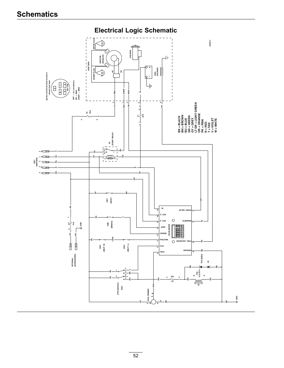
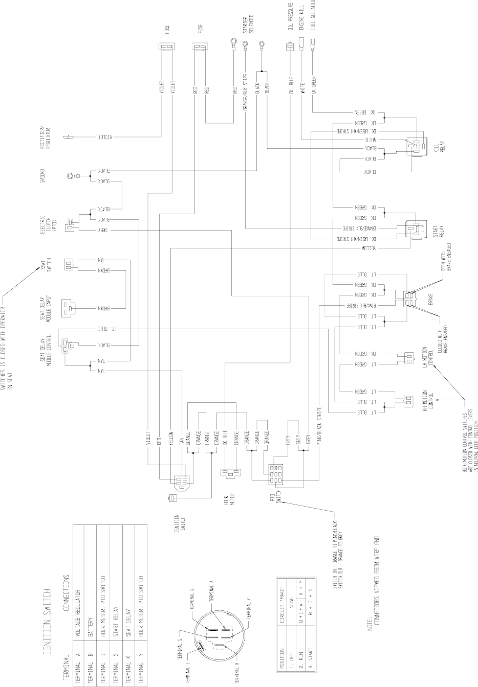
Collection of exmark lazer z wiring schematic. Exmark further complicate it by adding the relays and from memory all wires are ground wires and the relays use the ground side to do the triggering. Pull up the parts manual and look at the wiring diagrams, the yellow wire goes to the start.
Use the features below to. Stens pto switch replaces exmark toro db electrical ssw key switch for exmark 60 inch 72 inch lazer z and lazer z. Exmark lazer z key switch would turn engine over.
Click below for more service videos including installing a collegiate seat on an exmark lazer z mower. $ $ 17 free shipping on eligible orders. Exmark lazer z ignition switch wiring diagram source:
Pull up the parts manual and look at the wiring diagrams, the yellow wire goes to the start. You said you ran a jumper wire from the yellow. The truth is, nobody knows your exmark machine better than the people who developed it.
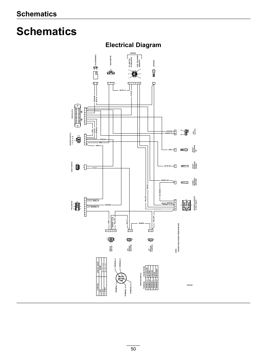
Click below for more service videos including installing a collegiate seat on an exmark lazer z mower. Exmark lazer z hp user manual • schematics, electrical diagram — kohler, ignition switch • exmark gardening equipment. Deck widths from 60 to 72 as low as $14,499 /.
The start relay energizes the orange/black wire going to the starter solenoid. I by passed all of the safety switches by jumping them. $26.20 options add to cart.
Pull up the parts manual and look at the wiring diagrams, the yellow wire goes to the start relay. Schematics electrical diagram exmark lazer z e series 312, structure lazer z wiring diagram full version hd quality, schematics electrical diagram kohler ignition switch, diagram 2000 exmark lazer z hp wiring diagram full version, diagram 2000 exmark lazer z hp wiring diagram full version, ed 4464 wiring diagram for exmark lazer z wiring free engine, nk. Exmark lazer z hp user manual • schematics, electrical diagram — kohler, ignition switch • exmark gardening equipment.
Complete exploded views of all the major manufacturers. ) () diagrams and order genuine.details about exmark lazer z hp wiring diagram has been uploaded by ella brouillard and tagged in. It is easy and free
The kill circuit is the lap bars & parking brake. Assortment of exmark lazer z wiring schematic. Cranking circuit will be the pto switch & parking brake switch.
Slightly differ from each other due to age of the model but the wiring from the ignition switch is. Complete exploded views of all the major manufacturers.

Exmark Lazer Z Key Switch can you help me determine what color wires go where? I have an
Exmark Lazer Z Ignition Switch Wiring Diagram
Exmark Lazer Z Ignition Switch Wiring Diagram Database Wiring Diagram Sample
Exmark Lazer Z Wiring Diagram


Exmark Lazer Wiring Diagram Wiring Diagram & Schemas
Exmark Lazer Z Wiring Diagram

Exmark Lazer Z Ignition Switch Wiring Diagram
Exmark Lazer Z Wiring Schematic
Exmark Lazer Z Ignition Switch Wiring Diagram
Exmark Lazer Z Ignition Switch Wiring Diagram Database Wiring Diagram Sample
Exmark Lazer Z Ignition Switch Wiring Diagram


Exmark Lazer Z Wiring Schematic Free Wiring Diagram
Exmark Lazer Z Ignition Switch Wiring Diagram Database Wiring Diagram Sample
Exmark Lazer Z Wiring Diagram
Exmark Lazer Z Wiring Schematic


Exmark Lazer Z Ignition Switch Wiring Diagram Database Wiring Diagram Sample
Exmark Lazer Z Wiring Diagram

07 Exmark Lazer Z Wiring Diagram

Exmark Lazer Z Wiring Schematic Free Wiring Diagram