
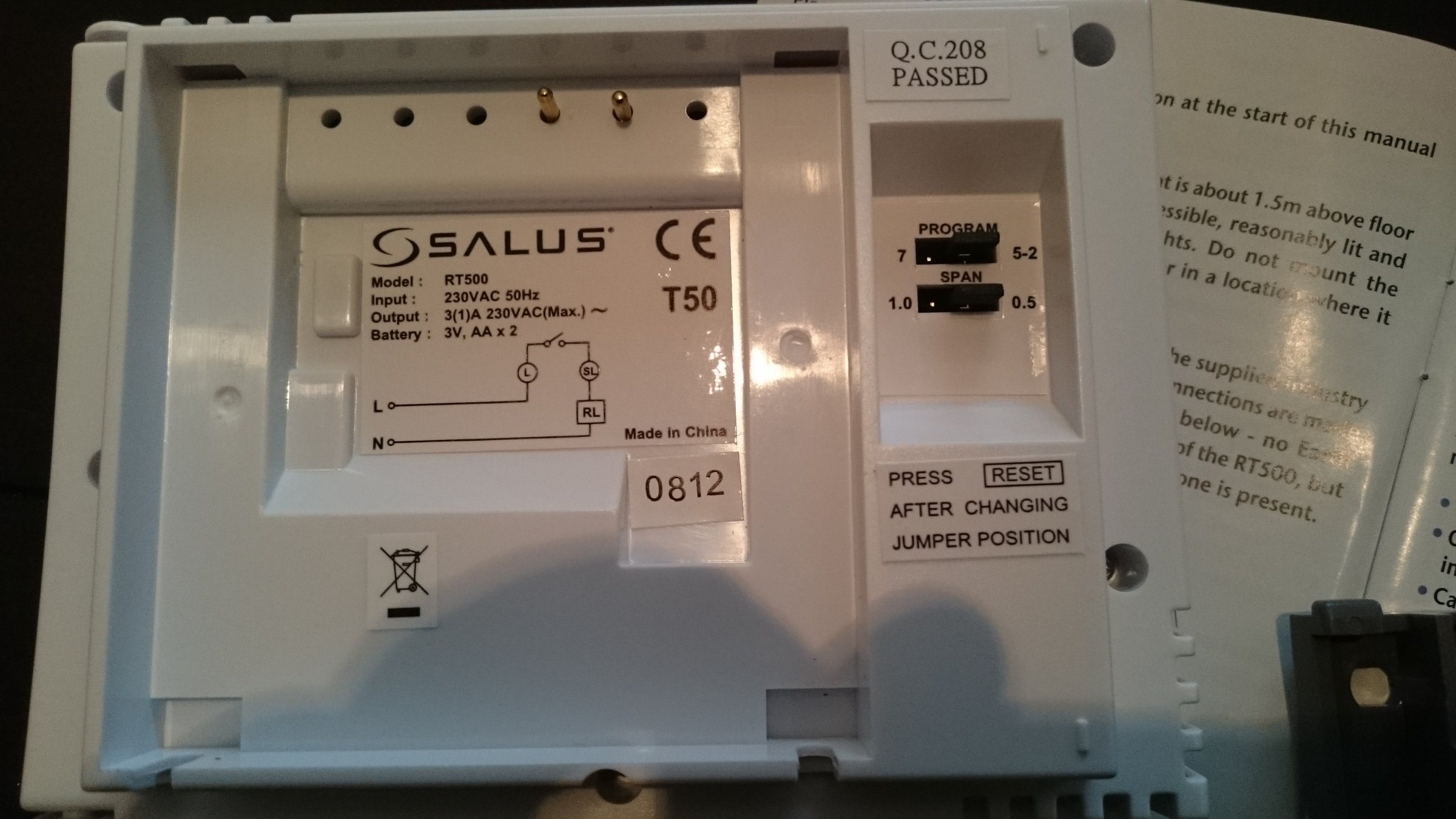
13 dec 2012 view count: Can only be used for 230v applications.
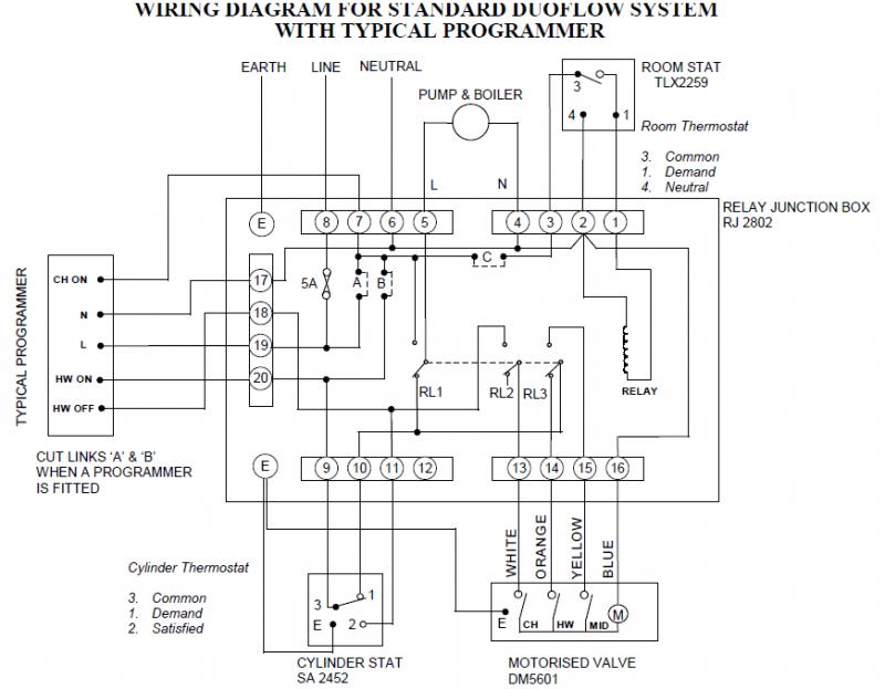
Sunvic Dm5601 Wiring Diagram Wiring Diagram
Mount the wireless receiver to the wall before wiring.

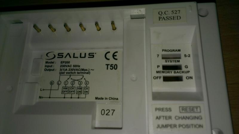
Salus ep200 wiring diagram. Menu id hot water control control interface various. All diagrams are in schematic form and earths have been omitted on the drawings for clarity. Always use the included strain reliefs and position them on the outer insulation layer of the cable.
Plumbing and central heating replies: Salus ep200 manual 001:89 21/11/10 23:44 page 5 Ep200/sp220 cylinder thermostat model no.
Salus ep101, sp120 n l 4 3 grasslin towerchron qe1 n l 2 4 t2001, t2001q e n l 7 sangamo m6 e 4 6 3 1 smiths centroller mk1 & mk2 n l 3 2 centroller 30 1 2 3/4 centroller 300, 980 n l 4 1 venner vennerette n l line load the quick and easy way to compare, upgrade and replace existing timeswitches these tables show the wiring conversion necessary. For ease of wiring, we recommend 1mm2 cable, although 1.5mm2 can also be used. Wiring of danfoss hsa3 diverter valve to salus ep200 martinhazell , 2 nov 2009 , in forum:
Salus vs10wrf quick manual pdf manualslib. The following criteria apply to the installation: Salus room thermostat diy at b q.
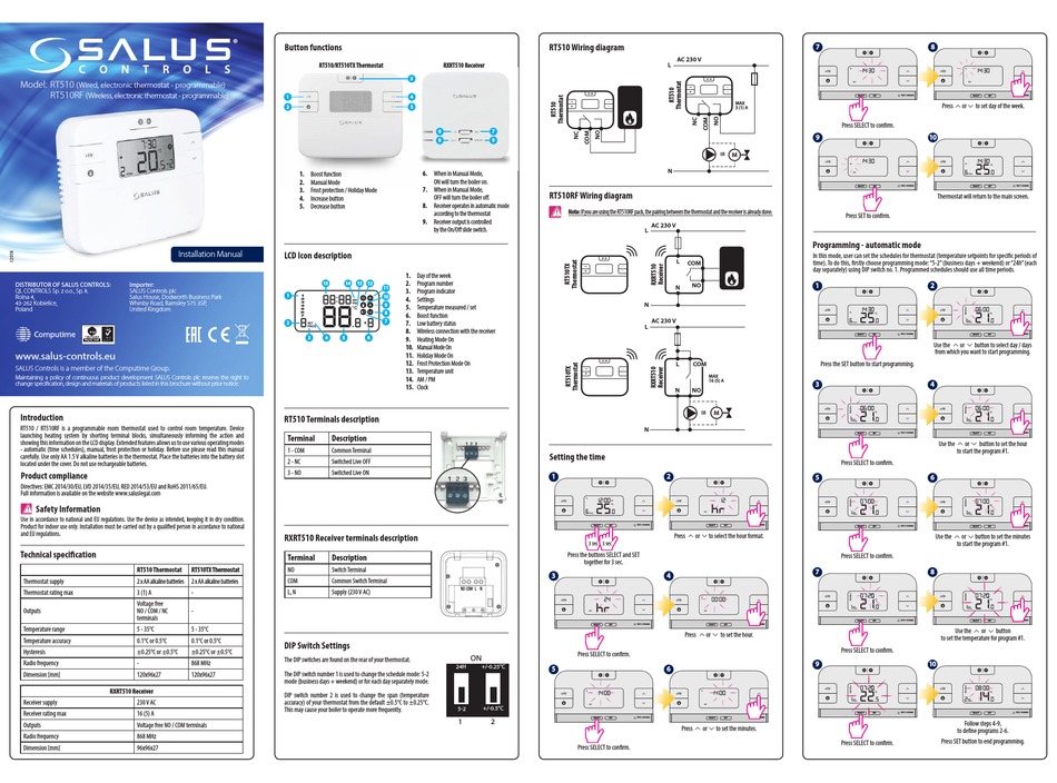
Links shown on diagram should be made by the installer. Salus rt510 installation manual pdf rt510rf quick manualzz termostato programável rt520 programmable room technical specification lcd icon rt310 digital thermostat wiring of to rt310i rt310tx stat controls uk de usuario 2 s on model wired ep101 instruction vs10wrf rf500 ideal logic combi 24 handleiding. Vaillant combi boiler wiring diagram.
Pair the wireless receiver a. Salus rt510 installation manual pdf manualzz rt310 digital room thermostat rt510rf wiring diagrams it500 controls installer mode of to s uk ep101 instruction a rt300 quickmanual de usuario 2 htrs230v 30 full user wired non diy at b q ert20rf wireless programmable kl08rf d emploi rt 520 rf des pages honeywell wall stat diynot. (nc) hws (no) hw ch hw ch off off on on ac mains in 11 10 9 4.
0020244997_06ecotecplusinstallationandmaintenanceinstructions 7 2 guaranteeandcustomerservice thank you for installing a new vaillant appliance in your home. 3 (1) a 2x spdt. • individual control of central.
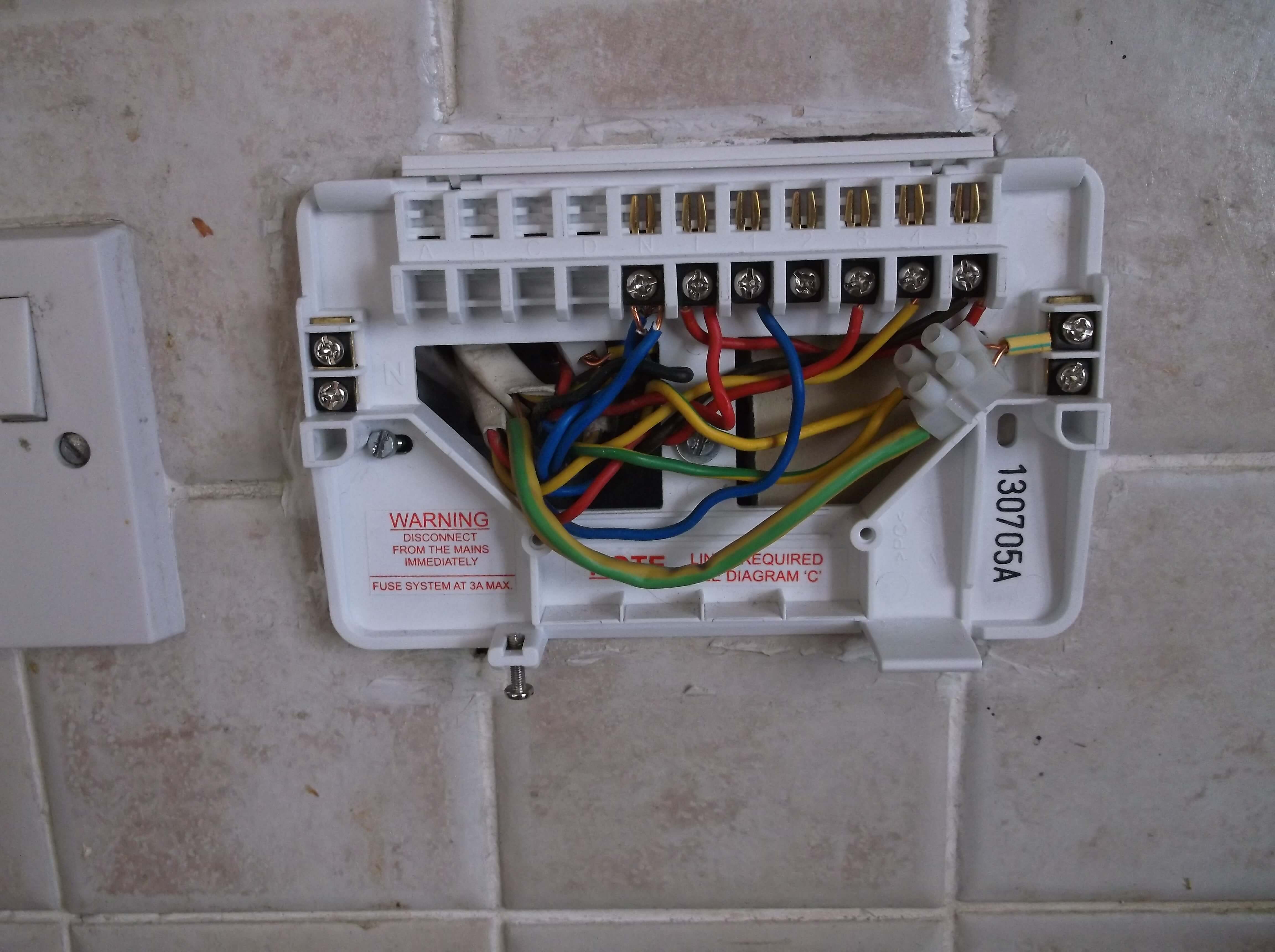
When replacing an existing programmer, the wiring conversion table (table 1) may be of assistance. Tc 100 blue n white (ch call) orange (hw call) grey (hw sat) yellow/green. •the incoming ac mains supply should be 230v ac and fused at 6 amps.
There are no comments to display. Press both test buttons at the same time for 5 sec, until the coloured power led shows the current configuration. For wiring to the zone valve/underfloor heating valve, check the manual of the valve.
Salus it500 full user manual full user manual (52 pages) salus stp1 wiring diagram wiring diagram (2 pages) salus rt 10 installation and operating instructions installation and operating instructions (1 pages) salus ert20rf instruction manual instruction manual (16 pages) All wiring should conform to the current ieee wiring regulations. The wiring centre includes diagrams for all standard heating systems.
2 channel programmer for timed control of central heating and hot water in a domestic system. Potential free relay rt rt 230v relay l sl the default factory configuration is relay. If the smart thermostat is wired via relay, step 5 (configuration) can be skipped.
Accepts no liability for any loss or damage arising from any errors or omissions that may be inadvertently contained within this diagram. • all wiring connections should be securely made, and be firmly gripped beneath the terminal square brass washer. Blue (n) brown (no) orange hw call (c) grey hw (l) e yellow/green n hw motorised valve model nos.sp/sbmv22 sbmv28 ac mains in (nc) hws (no) hw ch 12 13 15 14 11 10 9 8
Ct100 wiring centre model no. Manufactured in a flame retardant After installing the backplate in a suitable location, wiring connections can be made as shown above.
Sep 27, i have very little experience wiring boilers and will be required to wire a on the wiring diagram, there is a connecton called rt (for v). Accepts no liability for any loss or damage arising from any errors or omissions that may be inadvertently contained within this diagram. Using a wiring centre is a safe and convenient method of wiring a heating system, which makes system testing a simple task.
•optimum cable size for installation is.
programmers & timers DIYnot Forums

Gravity fed system Is Heating Only possible? DIYnot Forums
Salus EP200 wiring diagram DIYnot Forums
Change T6360B for Salus RT200 Help DIYnot Forums

Salus Digital Thermostat Wiring Diagram Wiring Diagram
Thermostat wiring santity check please (Honeywell > Salus) Overclockers UK Forums

Salus Digital Thermostat Wiring Diagram Wiring Diagram
2 channel thermostat to combi boiler DIYnot Forums


Salus Digital Thermostat Wiring Diagram Wiring Diagram

Salus Digital Thermostat Wiring Diagram Wiring Diagram
Change T6360B for Salus RT200 Help DIYnot Forums
Salus DIYnot Forums
Wiring up a Salus RT300RF and Worcester Greenstar Ri 12 DIYnot Forums
Problem with RF room stat (salus rt300rf) DIYnot Forums

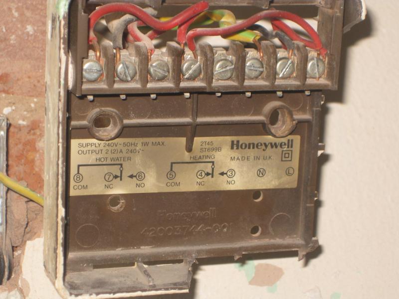
Wiring a Salus EP200 to replace Honeywell ST699 DIYnot Forums
Wiring up a Salus RT300RF and Worcester Greenstar Ri 12 DIYnot Forums
Obd Port Connector Wiring Diagram Wiring Diagram
Potterton Ep2002 Wiring Diagram Hack Your Life Skill

Heat Strip Wiring Diagram / Electric Heat Strip Wiring Diagram Popular Wiring A Heat Pump